The rain water as it passes through the atmosphere; picks up dissolved gases. When it comes in contact with the earth, picks up the suspended & dissolved matter. Thus the main impurities in the water can be broadly classified as under:
- Undissolved suspended solids
- Dissolved solids
- Dissolved gases
- Other impurities.
The water is used in industry or for drinking which requires certain specifications. The above mentioned impurities are removed through various processes and equipments to give suitable water for each application.
Filtration for removal of un-dissolved suspended solids:
This is commonly known as turbidity. The turbidity in the water ranges very widely from as high as 5,000 to 10,000 PPM in rainy season in river water to almost 0 PPM in bore well water. The turbidity can deposit of heating surfaces, strainers, cooling tower fins and cause clogging.
The turbidity removal is achieved through settling, clarification & filtration.
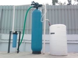
Pressure Sand Filter:
When the suspended solids are @ 50 – 100 PPM, the filters are used. For highly turbid waters, coagulation, settling is required.
The filtering media in these filters is fine sand. ( 16/32 mesh ) The sand is normally supported on a bed of graded pebbles and silex.
The filter unit has a nest of valves for service, rinse and backwash operation. The filters generally are of down flow configuration and backwash is in upwards direction. The dirt accumulated in service cycle is removed in backwash operation.
Activated Carbon Filter:
Activated carbon filter is one of the most widely used media for absorption of impurities. It is used for dechlorination, removal of organics and removal of odour.
The carbon filter comprises of pressure vessel, nest of valve or multiport valve, associated piping, and carbon media of specified quality depending on application supported by pebbles and silex.
Micron Filters:
These filters are of various types and capacities. Generally these are used after the above coarse filters so that the life is increased. They come in 50, 25, 10, 5, 1, 0.5, 0.2 and 0.1 micron rating. They are either absolute or nominal type. Nominal means @ 90 – 95 % particulate matter is trapped and absolute means 100 % particles are trapped. They come in various materials like PP, RBC, Sintered, SS etc. The weaving is also different like spun, wound, pleated, grooved etc.
Water Softening:
Water softener is commonly used process equipment for removing hardness in the raw water so as to make it usable for various applications like boiler feed, cooling tower make up, textile mills, laundries, AC plants, heat exchangers & for domestic use also.
The water softener is a cylindrical vessel containing strong acidic cation resins in Na form. When the hard water passes through the softener the resins exchange water hardness ( sum of calcium and magnesium ions ) and gives sodium ion to the water, that’s how one gets the soft water. The resins have a finite exchange capacity which needs to be restored by charging the resins with NaCl. The reaction can be shown as under :
CaSo4 ( raw water ) + R ( Na ) = R ( Ca ) + Na2 So4 --- Service cycle
R ( Ca ) + Nacl = R ( Na ) + Cacl2 ( drained out ) --- Regeneration cycle
The resins are generated by 10 – 13 % Nacl solution. The regeneration timing is @ 20 – 30 minutes followed by slow rinsing for 5 min. & fast rinsing for 5 – 10 min.
The softener can be in MS or FRP construction, with nest of valves or single multiport valve. The unit can be manual or automatic in operation.
The softener removes only hardness and sodium is given back to the water, hence TDS does not reduce.
DM Plants:
Global Aqua is one of the top DM plant manufacturers in pune. When the dissolved solids in the water are to be removed, Demineralisation is used many times. The DM plant essentially must have minimum two resin columns, Cation and Anion. The cation unit contains resins, which are in H form and Anion resins in service cycle are in OH form.
DM & MB Plant:
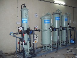
DM Plant process : The filtered raw water, when passed through a two bed DM plant, cation resins exchange all cations in water and the salts are converted to respective acids. This acidic water is passed through the anion resins, which exchanges the anions and the pure water is achieved. The reaction of the units can be shown as under :
CaSO4 + R ( H ) = R ( Ca ) + H2SO4 --- Cation service cycle
H2SO4 + R ( OH ) = R ( SO4 ) + H2O --- Anion service cycle
R ( Ca ) + Hcl = R ( H ) + Cacl2 --- Cation regeneration
R ( SO4 ) + NaOH = R ( OH ) + Na2SO4 --- Anion regeneration
The water coming out of Anion unit generally has following treated water quality :
Hardness : Nil
Conductivity : Less than 40 microsiemens
pH : 7.5 to 9.0
The two bed DM plant generally consists of two pressure vessels for accommodating cation and anion resins, nest of valves or multiport valve, piping, chemical tanks, testing kit and conductivity meter.
If the alkalinity in raw water is more, then the degasser tower is used to mechanically remove the alkalinity. This is done by passing the water after cation unit into the tower filled with media and the air is passed by using the blower, so that the water is scrubbed by air and the free carbon dioxide is removed through the vent resulting into alkalinity reduction at the outlet. This considerably reduces the ionic load on the DM plant. However, the cost of tower, sump and SS pump gets added into the system consuming more space & capital cost. The induction of this unit should be justified by the savings of NaOH used for the anion resins.
Some of the applications like pharma, high pressure boilers, electronic industry etc. require superior quality than above, in such cases, the mixed bed unit ( MB ) is used to further polish the water. The MB unit consists of two types of resins, cation & anion in the same column. The resins are separated by water during regeneration and mixed with air for service cycle.
RO PLANT: Residential / Commercial Units
Global Aqua is amongst the top ro plant manufacturers in pune. Reverse osmosis is the technology of removing dissolved salts and substances using the membranes and high pressure. The membrane is a type of filter having pore size of 0.0001 micron which means that the bacteria ( @ 0.4 micron ) and even the dissolved ions are removed from membrane and one gets very pure and tasty water.
RO Plant: (Global Aqua Site foto: RO System Manufacturer in pune)
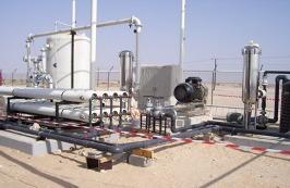
The raw water passes through the pressure sand filter first and then to the 5 micron cartridge and carbon cartridge or carbon filter. ( In our residential model – DRO 10, the sand filter is not considered ) The water is then pumped using high pressure pump into the membrane housing. The extra pressure filters the dissolved substances in the water and treated water is received from one end. However, the solids, which are rejected by the membranes are drained out through the reject port.
Typical recovery of the smaller plants can be from 15 % to 50 %. Higher recoveries are possible with adequate pretreatment.
Recovery means the % flow available for the product side.
Assuming, we are feeding 100 LPH water into the RO block using pump and the plant is operated at 30 % recovery, which means that 70 LTR of water would go to drain and 30 LTR would be available for production. This 70 LTR water would have the additional salts which are rejected by the membranes so as make product water.
As in case of softeners or DM plants, the RO plant does not require any regeneration. However, if pretreatment is given, it should be strictly monitored. For smaller systems, the cartridges need to be replaced on time.
In general replacement of cartridges should be done once in 6 months. The membranes in Indian conditions have life expectancy of @ 3 – 4 years. The major operating cost would be electrical consumption of high pressure pump apart from any pretreatment side dosing.
Basic R.O. Plant Principals:
A. Reverse osmosis process description.
Reverse osmosis, ion exchange, distillation and electrodialysis are the major processes used in industries.
Reverse osmosis is in general the most economical process for desalination of brackish water and sea water. As a widely accepted technology Reverse Osmosis became more and more competitive and is superior to the traditional thermal process when a comparison is made of capital investment and energy consumption.
In reverse osmosis the RO membrane acts as a barrier to all dissolved salts, inorganic molecules with a molecular weight greater than approximately 100. Water molecules on the other hand pass freely through the membrane creating a purified product stream. Rejection of dissolved salts varied between 95 to 99 %.
The application of R. O are numerous and varied and include desalination and purification of sea water and brackish water for drinking purposes, waste water recycling , food and beverage processing , bio medical separations, purification of drinking water, cooling tower makeup water, boiler feed make up water, and industrial process water. RO is often used for production of ultra pure water for use in the semiconductor industry, Power industry and pharmaceuticals / medical/ Laboratory application. Utilizing RO prior to DM / EDI plant dramatically reduces the operating cost.
B. How reverse osmosis works:
The phenomenon of osmosis occurs when pure water flows from a dilute saline solution through a semi permeable membrane into a higher concentrated saline solution. In osmosis process a semi permeable membrane is placed between two compartments having water of different concentrations. Semi permeable means that the membrane is permeable to some species not to others. Assume that the membrane is permeable to water but not to the salts. The membrane will allow water to permeate it to the either side. But salt cannot pass through the membrane. As a fundamental rule of nature, this system will try to reach equilibrium. That is it will try to reach the same concentration on both sides of the membrane. The only possible way to reach equilibrium is for water to pass from the pure water compartment to the salt containing compartment, to dilute the salt solution.
REVERSE OSMOSIS:
Pressure applied in excess of osmotic pressure reverses water flow direction. Hence this is termed as REVERSE OSMOSIS.
If a force is applied to the concentrate water column, the direction of the water can be reversed. This is the basis of the term REVERSE OSMOSIS. Since the membrane is not permeable to the salts. Hence reverse flow produces pure water from the salt solution to flow the solution of lower concentration.
With the help of high pressure pump, pressurized saline water is continuously pump to the Reverse osmosis module system. With the module, consisting of a pressure vessel(housing) and a membrane element, the feed will be split in a low saline product called permeate and a high saline brine called concentrate. A flow regulating valve called concentrate valve, controls the percentage of feed water that is going to the concentrate stream and the permeate which will be obtained from the feed. In case of spiral wound module consisting of a pressure vessel and a several spiral wound elements, pressurized water flows into the vessel and through the channels between the spiral windings of the spiral wound element. The feed water becomes more and more concentrated and enter the next element and at last exit from the last element to the concentrate valve where the applied pressure will be released. The permeate of the each element will be collected in the common permeate tube install in the center of each spiral wound element and flows to the permeate collecting pipe outside of the pressure vessel. The permeate or concentrate is collected and used as per requirement.
Recovery (%) = Permeate flow X 100
Feed flow
Salt passage(%) = Permeate salt concentration X 100
Feed salt concentration
Salt rejection (%) = 100 – salt passage